BUILD LOG 002 · IN LONG-TERM TESTING
Modern wiper blades on the original arms.
Printed adaptors so the modern blades from any parts store run on my '83 Supra's original wiper arms, without drilling them. Now in long-term testing on the car.
In long-term testing. Wipers are safety equipment. These adaptors are on my car and being tested over time: vibration, UV exposure, rain and time still need proving before they could be offered to anyone. Nothing on this page is for sale.
- Car
- 1983 Toyota Celica Supra (A60)
- Positions
- Driver, passenger, rear hatch
- Latest
- Revised ASA set, Rain-X blades
- On the car
- Since Sept 20, long-term testing
- Status
- IN LONG-TERM TESTING
01
The problem, and the plan
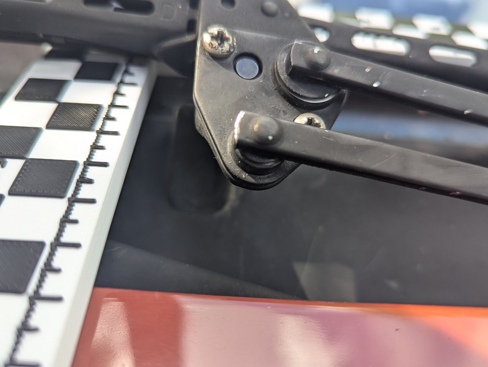
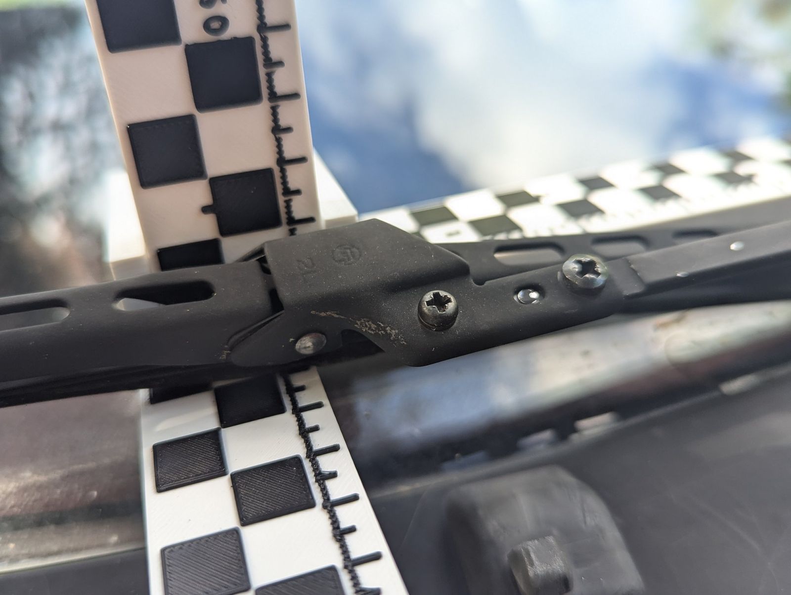
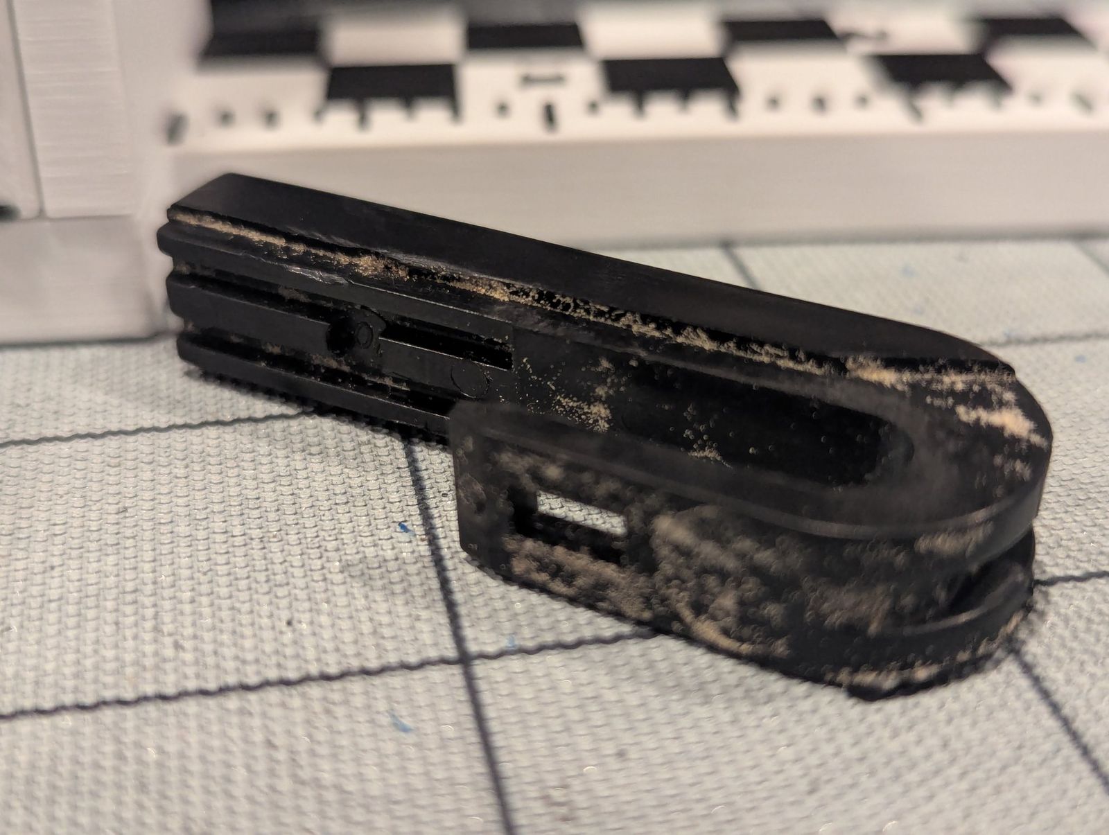
On the A60, each front blade clips into a black plastic carrier on the end of the arm. Two screws come through the arm and thread into the carrier, and alignment pins and bores keep it square. The carrier holds an old-style blade. The rear uses a plastic U-hook, and forty years shows.
The goal: run the modern blades you can buy at any parts store on the original arms, for all three positions, without drilling or modifying the arms. No dimensions are taken from anyone else's adaptor: everything comes from my own calipers on these parts and the published blade-connector standards.
First lesson: from photos alone, the front carriers looked like a pantograph linkage. With the parts in hand, the two holes turned out to be screw holes. Photos show that a feature exists, not what it does.
02
Let the shape do the work
Plastic is roughly a hundred times less stiff than steel. A flat plastic plate would need to be about 12 mm thick to match a thin steel one, and there's no room for that between the arm and the glass. So the shape has to carry it: a 12 × 8 mm box with 2.4 mm walls is about 26 times stiffer than a 12 mm-wide plate 2.66 mm thick. Printing makes that kind of shape possible where a flat cut part can't have it.
03
The blade end: nine test pieces (Aug 18)
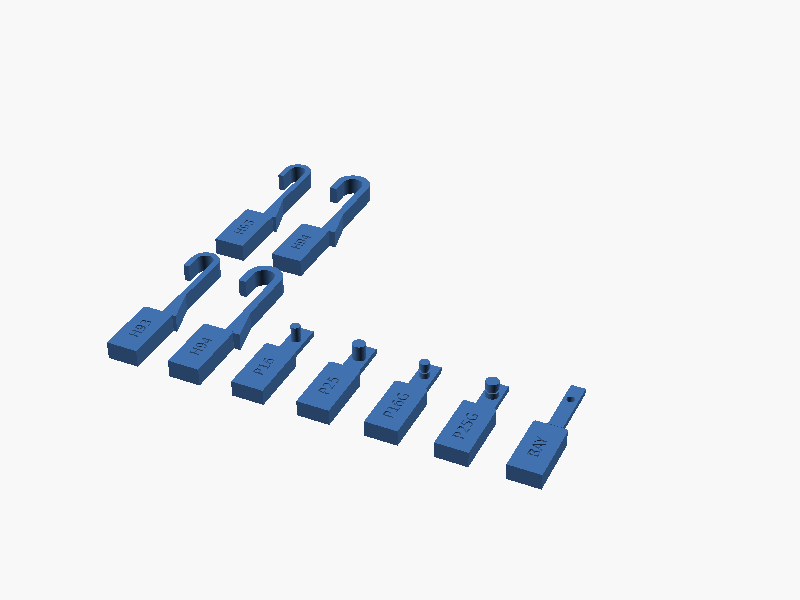
Modern blades clip onto a handful of standard arm ends. The common one in the US is the J-hook: a 9 mm-wide bar, 3 or 4 mm thick, curled over. I printed nine test pieces at the published dimensions, in PLA:
- J-hooks, 9 × 3 and 9 × 4 (two of each)
- side pins, 3/16 in and 1/4 in, plain and grooved
- a bayonet
The hooks went onto a real Bosch Micro Edge blade connector. Both fit, and the 9 × 4 felt more solid. The printed width measured 9.00 mm, right on the number.
Small lesson: the second insertion was easier than the first. That's PLA yielding on the first push, so the fit really was a hair tight. The usual suspect is the thickness, which the nozzle's extrusion width sets, rather than the width, which the stacked layers set.
04
The blade I actually wanted to run (Aug 24 to 26)
The blade I bought for the car, a Rain-X Latitude, didn't latch on my J-hook. The hook went in, but the connector's clip wouldn't close over it. I tried two routes side by side: narrowing the hook, and building the arm style the connector was made for.
The hook route gave me a mistake worth sharing. I printed a ladder of hook widths stepping 0.15 mm apart, and the rungs came out essentially the same width:
- the steps were smaller than the 0.20 mm layers on that axis, so the printer couldn't draw them
- the narrow section sat over an unsupported bridge that sagged
It probably cost me the blade's retaining tabs, too.
The other route won. The Rain-X connector is designed to fit several arm styles. One of them is a U-channel arm end with a window that the connector's push tab snaps up into, so the adaptor's blade end became that U-channel.
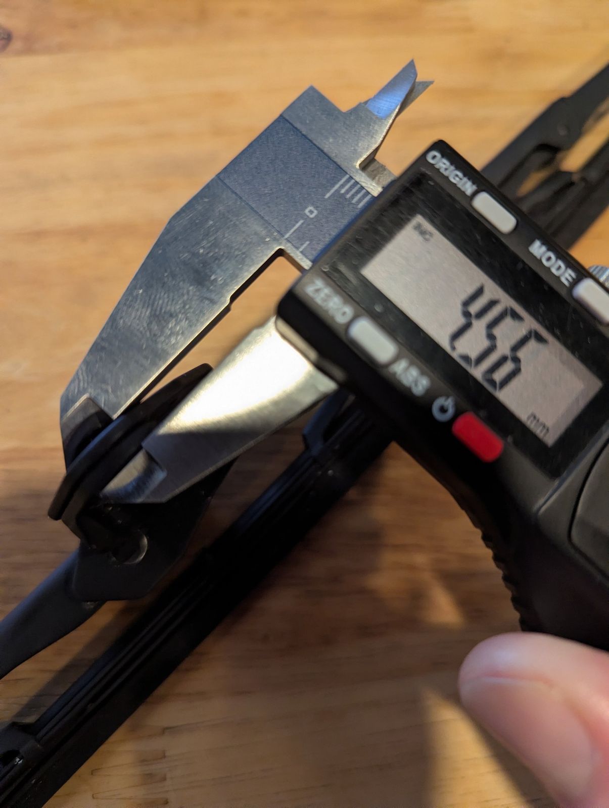
- The gauge beat the calipers. Calipers gave me 18.55 mm for the connector housing, and later 18.84. A printed ladder of collars, plus a coupon that checks the printer's own offset (it read 10.00 on 10.00, so no correction), said the 18.35 mm collar fit best, with room to spare. Neither caliper reading could be right: an 18.35 mm channel can't slide over an 18.84 mm housing. I'd been measuring the wrong spot.
- The deciding number was one I'd never measured. Short printed arm ends settled the rest in three rounds, and what decided it was the roof thickness: I'd guessed 2.5 mm, and 2.0 fit.
- Five tries at the wrong feature. I spent five attempts designing a press button into the channel before research showed the button belongs to the blade's connector. The arm end is passive; its window just has to catch the tab.
05
The car end, and all three adaptors (Aug 19 to 31)
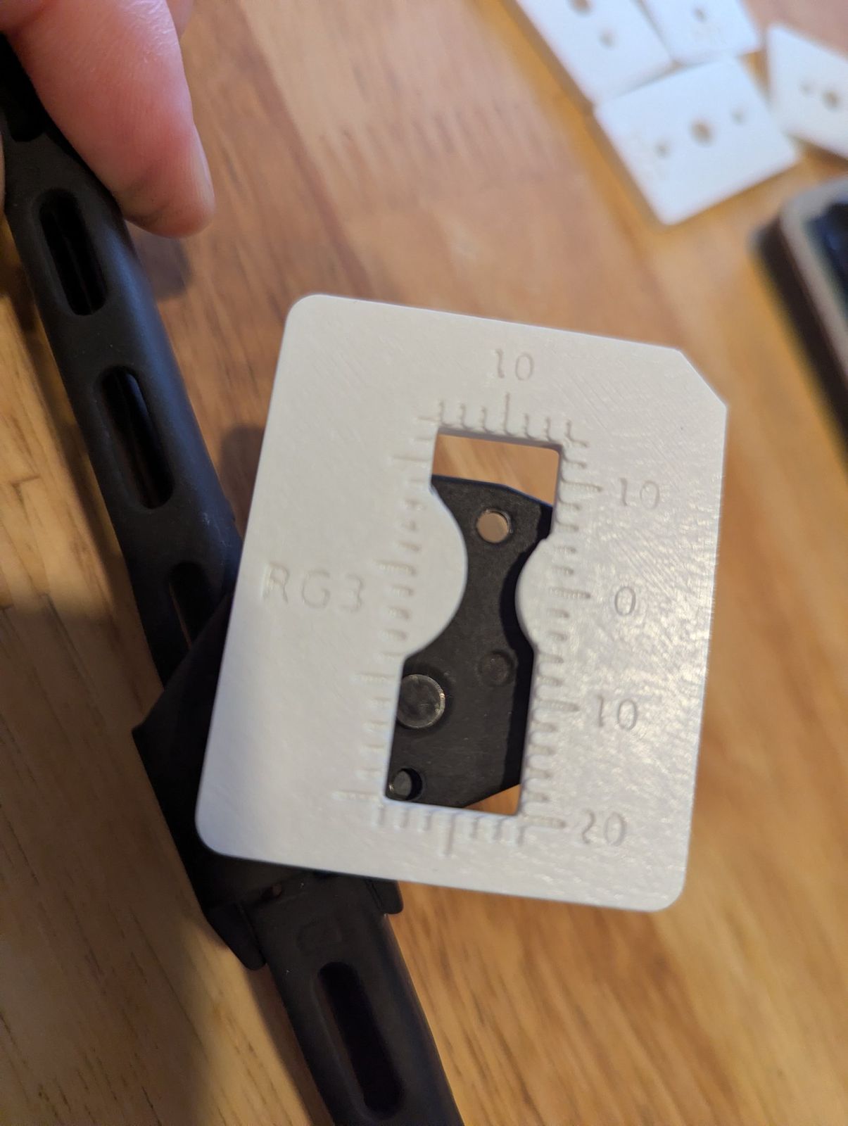
Printed gauges measured the arm ends too. The gauge below plugs into the two holes I already knew and puts a numbered window over the ones I didn't. It showed the driver-side hole pattern is a dog-leg, not a straight line. The passenger and rear arms carry a pin of their own, so those adaptors need a matching hole. The passenger and rear pattern plates seated on the car on the first try.
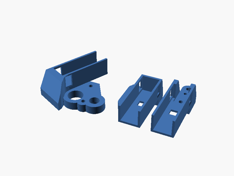
Then full adaptors for all three positions, on one print plate:
- Print orientation is decided in the design. Printed arm-face down, every bolt hole comes out vertical and support-free, and the blade channel opens upward.
- The joint took four tries. The joint between the mounting plate and the blade channel had to be strong without blocking the channel ends or the push-tab window.
- The pin came off. The driver side had an alignment pin standing up from the face that sits against the arm. It was the third locator on a part that already had two: a tapered bore that locks onto the arm's boss, and two screws. Removing it lets that face print flat on the bed. Contact with the bed went from 28 mm² to 1,324 mm², and support points under that face went from 1,221 to zero.
06
Screws, inserts and material (Sept 5 to 17)
Screws. The arm's original screw holes are 3.4 and 3.8 mm, so an M4 screw won't pass either one and M3 is the ceiling. I won't drill the arms. The thread used to live in the plastic carrier, so the adaptor gets brass M3 heat-set inserts. Small test coupons picked the hole size for them: 4.1 mm.
Material. PLA is for fit prototypes. The research parts move to ASA, which is UV-stable, handles heat, and needs the enclosed printer with the chamber warmed up. The ASA set is sliced with 4 walls and 40% infill, because the walls around the inserts carry the clamping load.
07
First fit, and a correction (Sept 18)
The first ASA set went on the car on Sept 18. Measured against the original blades, the new ones sat off to one side: the passenger blade about 15 mm and the driver blade about 31 mm toward the passenger side, and the driver blade lifted about 5 mm in the middle.
The fix: move the blade mount on both front adaptors to where the original carriers hold the blade, and lower the driver side. The revised set went to the printer that night.
08
On the car (Sept 20)
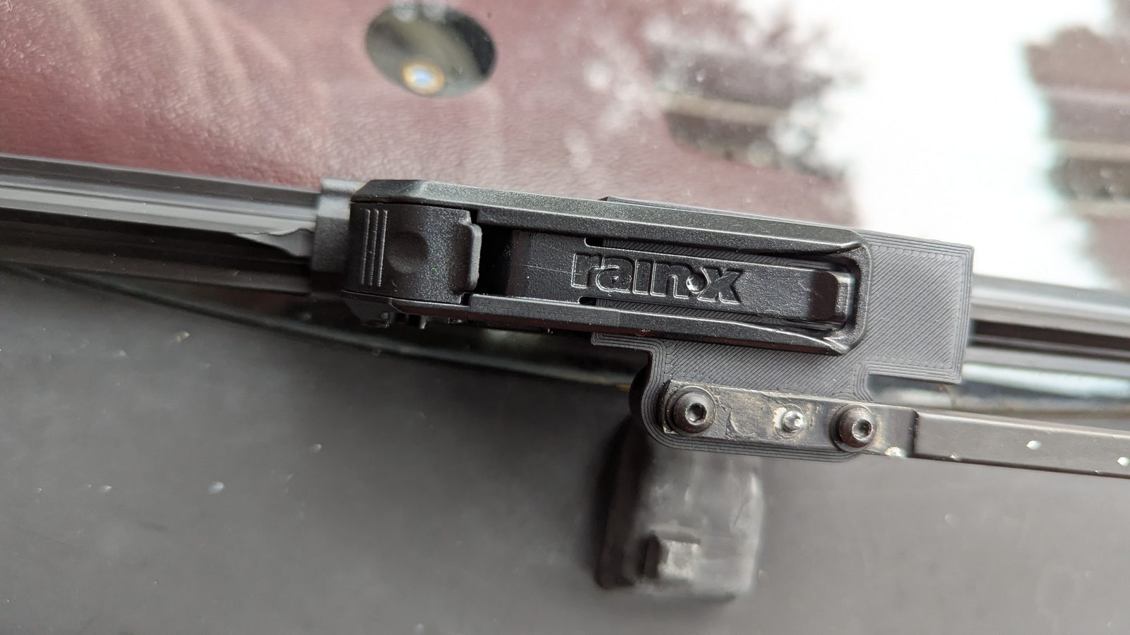
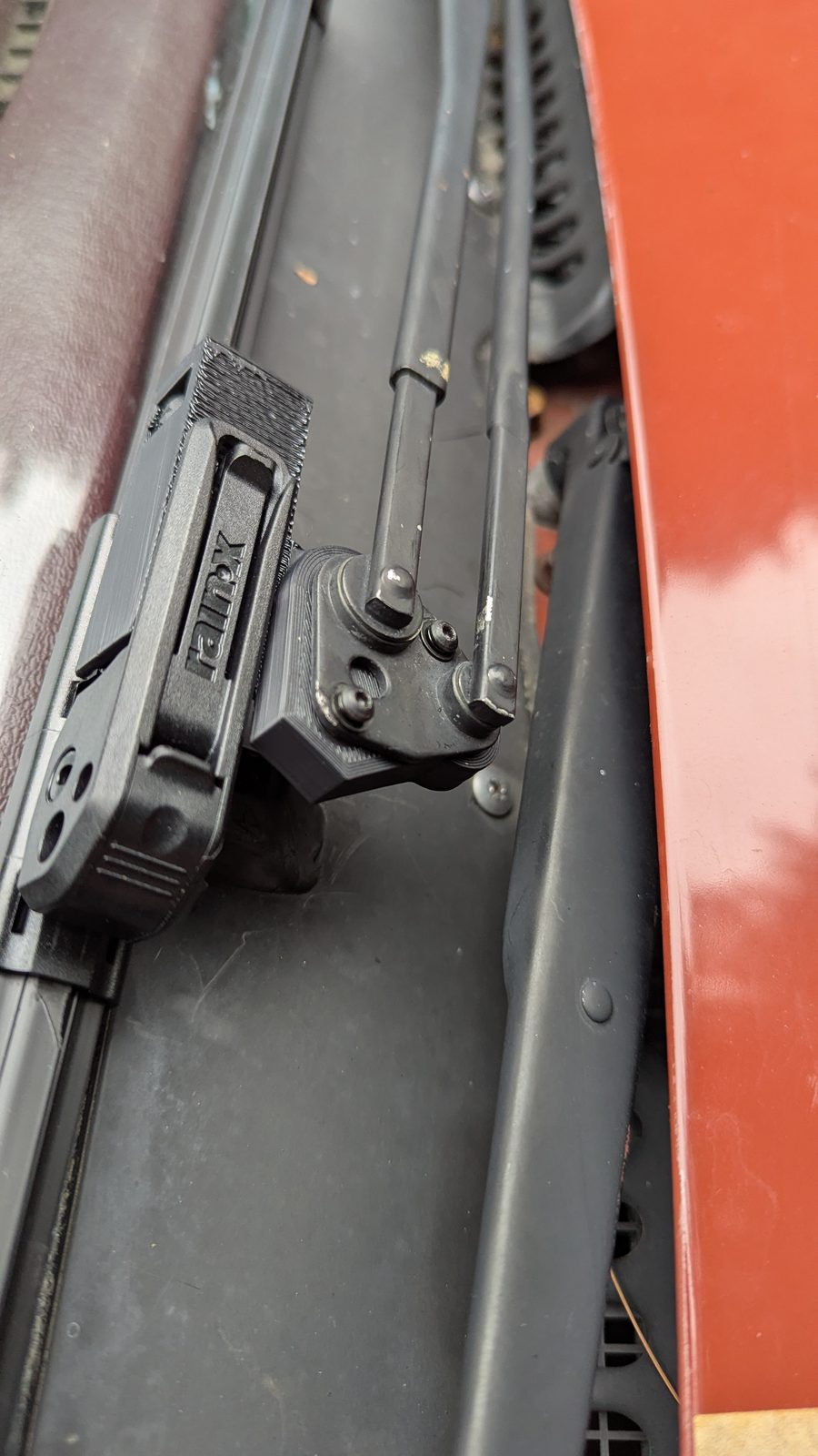
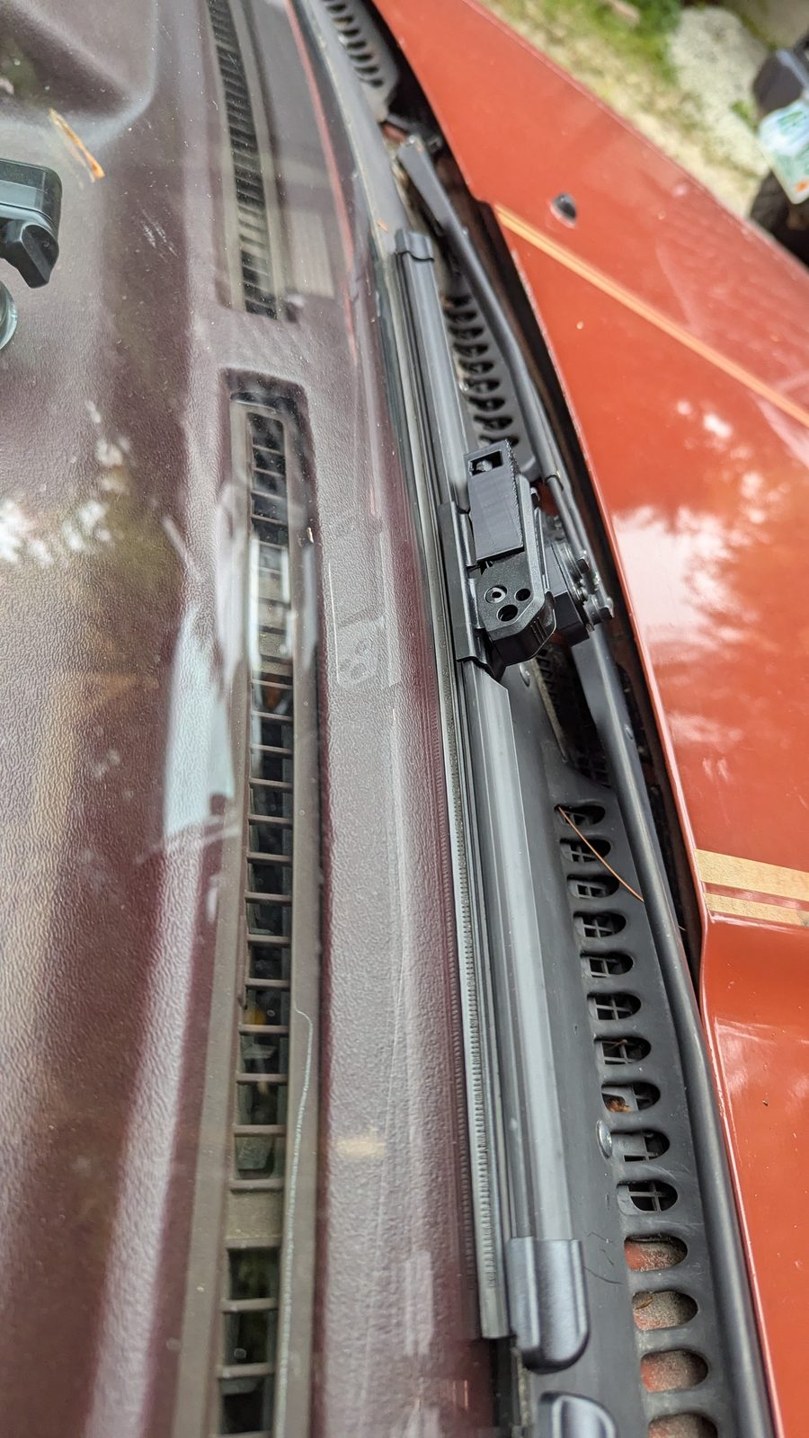
The revised ASA set is on the car, with Rain-X blades clipped into the printed adaptors on the original arms. The arms weren't drilled or modified. The clip below is a first powered sweep with the car parked.
09
Where it stands
- In long-term testing on my car since Sept 20. Not for sale.
- Still to prove: the full sweep at speed, wet and dry, heat, UV, vibration and time. This is the first part I've worked on where "it fits" isn't close to enough.
- Next: more photos and video as the testing builds up.